Furnace flame sensor symptoms: a diagnostic flow
Quick answer
The strongest flame-proving symptom is a gas furnace whose burners establish flame and then shut off shortly afterward, often followed by retries or ignition lockout. That sequence means the control lost acceptable proof of flame; it does not prove the flame sensor itself failed. Burner carryover, sensor position, wiring, grounding, polarity, gas input, venting, combustion, or the control can create the same result. Record the sequence and exact fault code, then leave cabinet-open testing to a qualified HVAC technician.
Common questions
- What is the clearest furnace flame sensor symptom?
- A strong clue is that the burners visibly light and then shut off shortly afterward, followed by another ignition attempt or a lockout. This shows that acceptable flame proof was lost, but it does not identify the sensor as the failed part.
- Can a dirty flame sensor cause furnace short cycling?
- Yes. Contamination on a flame rod can weaken the flame signal and cause the control to close the gas valve. Similar cycling can result from poor grounding, wiring, burner, gas, venting, combustion, or control problems, so the sequence and model-specific tests still matter.
- Can you bypass a furnace flame sensor?
- No. Never bypass, jumper, reposition, or defeat a flame-proving device. It is part of the furnace's gas safety controls. A qualified technician should diagnose why the control cannot prove flame and verify safe operation after the repair.
Source note: Reviewed September 2026 against current Carrier and Trane consumer guidance, OEM flame-signal service instructions, and U.S. Consumer Product Safety Commission carbon-monoxide guidance. Fault codes, timing, acceptable flame current, cleaning methods, and test points are model-specific; the current manual for the exact furnace controls.
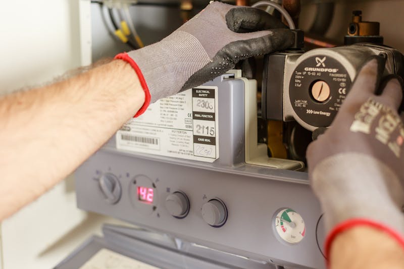
When a gas furnace lights and then loses flame shortly afterward, a dirty or damaged flame sensor is one possibility—but the shutdown pattern is not proof that the sensor failed. It means the furnace control did not receive acceptable proof of flame during that operating cycle.
The useful next move is to observe the sequence safely, record the exact fault code and furnace model, and let a qualified HVAC technician test the flame-proving circuit. Replacing or cleaning a sensor by guesswork can miss an unstable burner, a poor ground, damaged wiring, incorrect gas input, a venting problem, or a control fault.
Furnace flame sensor symptoms at a glance
| What happens | What it suggests | What it does not prove |
|---|---|---|
| Burners light, then go out shortly afterward | The control lost or never established acceptable flame proof | That the flame rod is dirty or defective |
| The ignition sequence repeats before stopping | The control is retrying under its programmed ignition logic | That every furnace uses the same retry count or timing |
| A flame-related code appears | The control detected a condition in its flame circuit or sequence | That a generic online code chart applies to this model |
| Heat works on some calls but not others | The flame signal or actual flame may be marginal or intermittent | Which component or condition is responsible |
| The inducer or igniter operates, but no burner flame appears | The sequence did not reach proven burner flame | A flame-sensor failure; there is no flame to prove yet |
| Burners run for several minutes before shutting down | A later safety, airflow, limit, control, or combustion event may be involved | The classic immediate flame-proving pattern |
Carrier’s flame-sensor overview describes the basic sequence: the sensor uses flame rectification to provide a small current to the control, and the control closes the gas valve when it cannot confirm flame. Trane likewise lists a dirty or faulty sensor among several reasons a main burner may shut off after ignition.
The distinction matters: “flame was not proved” is a control-board observation. “The sensor is bad” is a diagnosis that requires more evidence.
How flame proving fits the furnace sequence
A typical electronic-ignition gas furnace progresses through a thermostat call, inducer operation, pressure-switch proof, ignition, gas-valve opening, burner ignition, flame proof, and then indoor-blower operation. The exact order, timing, and fault response come from the furnace’s current service literature.
During flame rectification, the flame, sensor electrode, burner and furnace ground form part of a very small-current circuit. If actual flame is unstable, does not carry across to the sensing burner, misses the rod, or cannot complete a sound electrical return path, the board can lose proof even when the rod itself is intact.
That is why a furnace may present the same brief-lighting symptom for several different reasons:
- Contamination, damage, or incorrect position at the flame rod
- Loose, damaged, or high-resistance sensor wiring and connections
- Poor burner-to-chassis grounding, reversed polarity, or another supply issue
- Delayed or incomplete burner carryover
- Incorrect gas input or unstable combustion
- Intake, vent, condensate, or pressure-related problems on applicable equipment
- A fault in the ignition control
OEM documents show why generic thresholds are unsafe. A Trane furnace manual, for example, distinguishes low flame-sense, grounding, lockout, pressure-switch, and control codes. Lennox’s flame-signal measurement instruction specifies a meter arrangement for the covered control. Neither document establishes a universal code, test point, or acceptable reading for a different furnace.
What homeowners can observe safely
Keep the furnace assembled and stay outside gas, combustion, and electrical compartments. The goal is to give the service technician a repeatable symptom history, not to prove the component yourself.
- Act on hazards first. If a carbon-monoxide alarm sounds or anyone has possible CO symptoms, move people and pets outside and call 911. The U.S. Consumer Product Safety Commission says to get outside to fresh air immediately if CO poisoning is suspected. If you smell gas or hear hissing, leave without operating switches and contact emergency services or the gas utility from a safe place.
- Confirm the complaint. Note whether the thermostat is calling for heat, whether burner flame actually appears, when it disappears, whether another attempt follows, and whether the circulating blower starts. Observe only through the factory viewing port if the furnace has one.
- Record the code before power is interrupted. Photograph the status light or copy the displayed message. Then find the code table on the furnace label or in the exact model manual. Do not substitute a code chart for another brand or series.
- Check only ordinary owner items. Verify thermostat settings and inspect the filter without entering a service compartment. The winter HVAC preparation checklist covers low-risk seasonal observations.
- Stop repeated resets. A reset may erase useful fault history without correcting the cause. Do not cycle power repeatedly, move the sensor, adjust burners, open gas fittings, or bypass any safety.
Our DIY vs. professional HVAC repair guide explains why flame sensing belongs on the professional side of the boundary. Review the carbon monoxide and HVAC safety guide separately for alarm placement, exposure symptoms, and emergency response.
A technician’s flame-proving diagnostic flow
Qualified technicians should use the exact furnace service manual, current safety procedures, calibrated instruments, and applicable gas and electrical requirements.
1. Preserve the sequence evidence
Capture active and stored faults before resetting power. Confirm the model, serial number, control part number, thermostat call, active stage, and each completed step in the ignition sequence. Distinguish “no ignition,” “flame established then lost,” and “flame remained present but the signal was unacceptable.”
2. Verify the actual flame and combustion system
Follow the OEM procedure to inspect ignition, burner carryover, flame stability, sensor engulfment, gas supply and input, combustion air, venting, condensate handling, and safeties that apply to the equipment. A flame rod cannot prove a flame that is absent, unstable, or not positioned as the furnace was designed to deliver it.
Combustion and venting faults require correction before treating the electrical signal as an isolated sensor problem. Never use the safety control as a substitute for combustion analysis or heat-exchanger and vent inspection where those checks are indicated.
3. Inspect the complete sensing path
With power and fuel controlled according to the service procedure, check the electrode, porcelain insulator, mounting, lead, terminals, burner assembly, chassis connections, polarity, neutral, and ground path. Look for contamination, cracking, looseness, corrosion, misalignment, damaged insulation, or a prior incorrect replacement.
4. Measure flame current by the exact manual
Use a meter capable of the required DC microamp measurement and connect it only as the furnace or control manufacturer specifies. Record the signal during ignition and steady operation, then compare it with the exact model’s acceptable range. Do not import a “universal” microamp target from another control.
The measurement must be interpreted with actual flame quality and the electrical return path. A weak result can implicate the rod, but it can also expose grounding, polarity, wiring, burner, positioning, gas, or control conditions.
5. Correct the cause and prove the repair
Clean or replace the sensor only when the OEM procedure and evidence support that action. Use the specified method and correct part; an abrasive or substitute part that is acceptable for one design is not automatically acceptable for another.
After correction, verify fault history, flame signal, full heat cycles, temperature rise or airflow checks required by the manual, and safe combustion and venting. Document the before-and-after evidence instead of writing only “cleaned flame sensor.”
When the symptom points somewhere else
If the burners never ignite, investigate the sequence before flame proving: thermostat input, inducer, pressure switches, ignition source, gas supply, gas valve command, and related safeties according to the model literature. If burners stay on but the blower delivers cool air, a staging, airflow, duct, or control problem may be more relevant.
If the homeowner’s main complaint is that the furnace is blowing cold air, classify when the air turns cold and whether the thermostat is still calling for heat before narrowing the fault to flame proving. Cold air at startup, between cycles, after shutdown, and after established heat are different patterns.
Do not turn a single flame-sense fault into a furnace-replacement verdict. The furnace replacement warning-sign guide explains how safety, verified repair scope, equipment condition, reliability, and replacement cost belong in that separate decision.
Your next step
Homeowners: Record one observed heat call, the exact fault code, furnace model, filter condition, and recent service history in the HVAC maintenance log. Send that information to a qualified HVAC company and ask what evidence will separate the sensor from burner, grounding, wiring, gas, venting, and control causes.
HVAC professionals: Attach the sequence, OEM fault definition, flame-current result, combustion and grounding findings, corrective action, and post-repair verification to the work order. That record supports a defensible diagnosis and prevents an unnecessary sensor or control-board replacement.
Brief burner operation followed by shutdown is the key symptom to recognize. Treat it as the beginning of flame-proving diagnosis—not permission to bypass a safety, clean a part blindly, or declare the flame sensor failed.
Continue the furnace diagnostic path safely
Use these resources to document the fault, protect occupants, and keep diagnosis separate from repair-or-replace decisions.
- HVAC maintenance log
Record the ignition sequence, fault code, filter condition, and service history before the visit.
- DIY vs. professional HVAC repairs
Keep combustion, gas, flame-signal, and cabinet-open testing with qualified personnel.
- Carbon monoxide and HVAC safety
Review CO alarm placement, exposure symptoms, and the emergency-response boundary.
- Furnace replacement warning signs
Use verified safety, condition, cost, and reliability evidence for a separate replacement decision.

ThermalTechPro Team
Independent trade-focused editorial team