Heat pump short-cycling diagnostic checklist
Quick answer
Heat pump short cycling can start with a thermostat or control issue, restricted airflow, equipment oversizing, a safety opening, defrost behavior, an electrical fault, or a refrigerant-circuit problem. Record the exact sequence and operating conditions before replacing parts or changing charge.
Common questions
- How short is too short for a heat pump cycle?
- There is no universal minute threshold for every heat pump. Weather, load, capacity staging, thermostat logic, defrost, and model controls all matter; compare the observed sequence with current OEM documentation.
- Can a dirty filter make a heat pump short cycle?
- Yes. Restricted airflow can change coil conditions and may open a temperature or pressure protection. If a clean, correct filter does not resolve the problem, the full airflow path and blower setup need professional evaluation.
- Should a homeowner keep resetting a tripped heat pump breaker?
- No. A repeated trip indicates an electrical or equipment fault. Leave the circuit off and have a qualified technician diagnose it.
Source note: Reviewed August 2026 against Trane short-cycling guidance, DOE HVAC quality-installation guidance, OSHA electrical safety requirements, and EPA refrigerant rules. Cycle behavior and diagnostic limits remain model-specific.
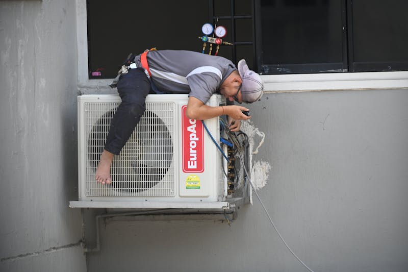
A heat pump that starts, stops, and restarts without delivering a normal heating or cooling cycle is giving you a symptom—not a diagnosis. Short cycling can originate in the thermostat, airflow system, equipment selection, defrost controls, electrical circuit, refrigerant circuit, or a protective control doing exactly what it was designed to do.
The fastest safe diagnosis begins with a timeline. Record what starts, what stops, which safety or code appears, and what conditions were present before touching setup values or replacing parts.
Confirm that it is actually short cycling
Modern heat pumps can stage, modulate, satisfy a small load quickly, pause between control calls, or enter defrost. Those behaviors can look unusual without indicating a failure.
Document:
- Thermostat mode, setpoint, room temperature, and active schedule.
- Outdoor and indoor conditions.
- Heating, cooling, auxiliary heat, or defrost indication.
- Which components start: indoor blower, outdoor fan, compressor, or backup heat.
- Time and event sequence rather than a single cycle length.
- Fault codes and whether a thermostat call remains present when operation stops.
- Zone position and any demand-response or energy-management input.
Compare the sequence with the current equipment and thermostat documentation. Do not impose one cycle-time rule on every single-stage, two-stage, variable-capacity, ductless, or dual-fuel system.
Homeowner checks and stop points
Homeowners can rule out several low-risk issues:
- Check thermostat settings. Confirm the mode, schedule, setpoint, and fan selection. Replace batteries if the model uses them.
- Install the correct clean filter. A filter that is dirty, incorrectly sized, or too restrictive for the system can reduce airflow.
- Open normal supply and return paths. Move furniture away from grilles and make sure registers have not been closed in an attempt to balance rooms.
- Clear outdoor obstructions. Remove leaves or snow around the unit without opening panels, chipping ice, or using heat.
- Record codes and sounds. A short video of the thermostat and equipment sequence can help the service technician.
Stop and call a professional for repeated breaker trips, burning odor, damaged wiring, persistent heavy ice, refrigerant suspicion, or any work requiring a cabinet to be opened. Do not defeat a safety, force a contactor, or repeatedly reset the system.
Technician diagnostic sequence
1. Reproduce the event and preserve fault evidence
Retrieve available fault history before cycling power. Observe the thermostat call, control outputs, indoor blower, outdoor unit, and shutdown reason. A safety opening after startup points down a different path than a call that disappears normally.
Verify thermostat location, sensor agreement, wiring, configuration, staging, setbacks, and any equipment interface. A thermostat affected by a supply register, sun, a draft, or an incorrect system profile can create erratic demand.
2. Verify airflow and heat transfer
Check the filter, indoor and outdoor coils, blower setup, wheel or fan condition, dampers, zoning, registers, and duct system. Record pressure and temperature evidence at the failing mode and stage.
Use the external static-pressure diagnostic workflow with the exact blower data rather than assuming a universal pressure limit. Restricted airflow can open a protection; excessive airflow or a setup error can also distort refrigerant and temperature evidence.
3. Compare capacity with the load
Oversized fixed-capacity equipment may satisfy the thermostat rapidly, especially during mild weather or when only a small zone is open. But short runtime alone does not prove oversizing.
Review the room-by-room load calculation, selected equipment performance, zoning minimums, duct capacity, thermostat cycles, and commissioning results. The Manual J, Manual S, and Manual D handoff explains how load, selection, and duct design connect.
4. Follow the control and safety sequence
Use the wiring diagram, sequence of operation, and fault documentation. Check whether a pressure, temperature, condensate, motor, communication, or other safety changes state before shutdown. Determine why it changed instead of bypassing it.
For communicating and variable-capacity equipment, verify matched components, addressing, firmware or configuration requirements, sensor inputs, and the manufacturer’s diagnostic process. Conventional voltage checks alone may not describe a networked control fault.
5. Separate normal defrost from a fault
In heating mode, the outdoor coil can frost and the system may periodically reverse to defrost. Indoor airflow, outdoor fan behavior, auxiliary heat, vapor, and sound can change during that event.
Compare initiation, termination, sensor readings, fan behavior, and timing with the specific OEM sequence. Investigate a sensor, board, airflow, charge, or heat-transfer problem only after confirming the observed event is outside that sequence.
6. Evaluate electrical operation safely
Inspect supply condition, connections, contactor or relay operation, capacitors where used, motors, and compressor evidence under the employer’s electrical safety program and OEM procedure. OSHA requires de-energization, lockout/tagout, stored-energy control, and verification except where a defined qualified-person exception applies.
An electrical component may fail because of a loose terminal, motor problem, abnormal supply, or excessive cycling. Correct the cause, not just the damaged part. Our capacitor vs. contactor comparison covers the symptom differences.
7. Evaluate the refrigerant circuit last, not first
After airflow, load, controls, and electrical operation are established, use the OEM procedure to evaluate pressures, temperatures, superheat, subcooling, sensors, valves, and protections. Do not adjust charge to chase a generic reading.
Connecting gauges or opening the circuit requires the appropriate EPA Section 608 certification, and refrigerant must not be intentionally vented. Find and repair leaks under the applicable procedure rather than repeatedly adding refrigerant.
8. Verify the repair through a complete sequence
Restore panels, guards, sensors, and safety functions. Operate the relevant modes and stages long enough to verify stable control, airflow, heat transfer, electrical behavior, and shutdown. Preserve before-and-after measurements and fault history in the job record.
Quick symptom map
| When operation stops | Evidence to capture next |
|---|---|
| Thermostat call disappears | Sensor location, schedule, staging logic, zone demand |
| Call remains but outdoor unit stops | Fault code, safeties, control output, electrical sequence |
| Indoor blower stops or changes first | Blower command, motor fault, static pressure, filter and coil |
| Shutdown follows frost or ice | Airflow, defrost sequence, sensors, refrigerant evidence |
| Only one zone causes the fault | Bypass strategy, minimum airflow, damper position, duct design |
| Breaker or protection opens | Leave de-energized; follow qualified electrical diagnosis |
Bottom line
Heat pump short cycling is solved by identifying which command or protection ends the cycle. Start with the recorded sequence, verify airflow and load, follow controls and safeties, separate normal defrost, and only then evaluate electrical and refrigerant causes.
For system fundamentals, read how heat pumps work. Persistent or hazardous symptoms deserve a qualified technician with the current wiring, charging, and control documentation for that exact model.
Sources and image credit

ThermalTechPro Editorial Team
Independent trade-focused editorial team