HVAC static pressure test diagnostic workflow
Quick answer
Total external static pressure is the sum of the return-side and supply-side pressure magnitudes measured across the air-moving equipment at a documented operating condition. Compare that result and each component pressure drop with the exact equipment and blower data; there is no universal pass/fail number for every system.
Common questions
- What does high external static pressure mean?
- It means the blower is operating against more resistance than the selected equipment data allows at that test condition. The reading does not identify the restriction by itself; return, filter, coil, supply, zoning, and duct measurements help locate it.
- Can static pressure prove airflow by itself?
- Not always. Static pressure can be paired with the exact blower performance table or approved commissioning method, but blower setup, motor control, test location, and system configuration all affect the inference.
- Should every system be judged against 0.5 inches of water column?
- No. Published limits and blower performance vary by furnace, air handler, fan coil, accessories, and operating mode. Use the current data for the exact model and configuration.
Source note: Reviewed August 2026 against DOE HVAC quality-installation guidance and ACCA duct-design resources. Test locations, pressure limits, airflow tables, and correction steps must come from the installed equipment and accessory documentation.
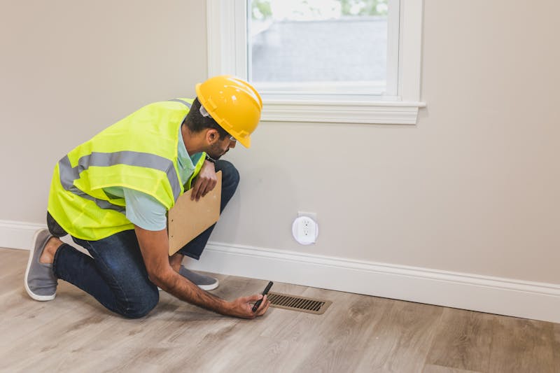
An HVAC system can have a clean coil and a powerful blower yet still deliver poor comfort because the air path is too restrictive. An external static pressure test gives that airflow problem a measurable shape. Done well, it tells the technician how hard the blower is working and where the pressure budget is being spent.
The test is most useful when it is treated as a commissioning record, not a single number. Equipment model, blower setting, filter condition, zoning state, and probe locations all belong beside the readings.
What total external static pressure measures
Static pressure is the force the fan works against in the air distribution system. A technician measures pressure at defined points on the return and supply sides of the air-moving equipment. Because return pressure is normally negative relative to the test reference and supply pressure is positive, total external static pressure (TESP) is calculated by adding their absolute magnitudes.
TESP does not automatically include every internal or external component. The equipment manufacturer’s diagram defines the boundary. On one installation, a coil or filter may be outside the rated appliance; on another, the relevant blower table may account for a different configuration.
That is why two measurements with the same numeric result can mean different things.
Why the reading matters
The Department of Energy identifies adequate airflow, correct equipment sizing and matching, correct refrigerant charge, and sealed ducts as parts of quality HVAC installation. Static-pressure testing supports that work by helping a contractor:
- Verify an installation before turnover.
- Investigate weak airflow, noise, hot or cold rooms, and repeated limit trips.
- Check whether a filter, coil, return, supply, or zone configuration consumes excessive pressure.
- Compare an installed system with the exact blower performance data.
- Establish a baseline for later maintenance calls.
Pressure is evidence about the air path. It is not a substitute for temperature, airflow, electrical, control, or refrigerant measurements when those are needed.
Prepare the test condition
Before collecting readings, document a repeatable operating state:
- Record the furnace, air-handler, fan-coil, indoor-coil, filter, and major accessory model numbers.
- Obtain the current OEM pressure limit, blower table, and test-location guidance for that configuration.
- Confirm the blower speed or airflow command being tested.
- Note whether the system is in cooling, heating, fan-only, auxiliary heat, or another mode.
- Place all zones, dampers, registers, doors, and panels in the position required by the commissioning procedure.
- Record filter size, type, age, and observed condition.
- Allow operation to stabilize as directed by the equipment manufacturer.
Opening a cabinet can expose electrical and moving hazards. Trained personnel should follow the employer’s safe-work procedures and the equipment instructions when installing or using pressure test ports.
Diagnostic worksheet
Use a worksheet that captures both the result and the conditions that produced it.
| Field | Record |
|---|---|
| Job and timestamp | Address or job ID, date, technician |
| Equipment | Indoor unit, coil, filter, accessories, zoning controls |
| Operating state | Mode, stage, blower tap or command, active zones |
| Return pressure | Reading and exact probe location |
| Supply pressure | Reading and exact probe location |
| Calculated TESP | Sum of return and supply magnitudes |
| Component drops | Filter, coil, accessory, or section readings where approved |
| OEM reference | Document name, revision, allowed external pressure, blower table row |
| Airflow evidence | OEM table result or other approved airflow test |
| Corrective work | What changed and why |
| Final verification | Repeated readings at the same condition |
Take a photo or sketch of each port location. A number without a location is difficult to reproduce and can be compared with the wrong pressure boundary later.
Turn readings into a diagnostic path
Start with the total
Compare TESP with the exact published limit and blower data. If the reading is outside the allowed range, do not immediately increase blower speed. A higher command can change airflow and noise while leaving the restriction in place.
If TESP is within the published range but comfort remains poor, check the actual airflow distribution, room loads, temperature change, duct leakage, controls, and equipment capacity. Acceptable total pressure does not prove every branch receives its design airflow.
Split return and supply
The two sides indicate where to continue:
| Pattern | Investigate, without assuming |
|---|---|
| Return magnitude dominates | Filter selection or condition, return grille area, collapsed or undersized return duct, closed door pressure, obstructions |
| Supply magnitude dominates | Indoor coil condition, restrictive supply fittings, undersized trunk or branches, closed registers, dampers, zoning configuration |
| Both sides are elevated | Multiple restrictions, incorrect test boundary, high airflow command, or a broadly undersized distribution system |
| Total appears low but delivery is poor | Low blower command, wrong motor setup, duct disconnection or leakage, open bypass, measurement-location error |
These patterns narrow the search; they do not diagnose the component on their own.
Measure component pressure drops selectively
When the equipment documentation permits it, pressure readings across a filter, coil, or accessory can identify where resistance is concentrated. Compare the result with manufacturer data at the relevant airflow and condition. A filter pressure drop that is reasonable at one airflow may be unacceptable at another.
Avoid drilling ports until you have confirmed safe locations. Coils, wiring, refrigerant tubing, heat exchangers, drains, and structural features may be close to the sheet metal.
Correct, then repeat the same test
After replacing a filter, correcting a damper, repairing a duct, cleaning an approved component, or changing an authorized setup, repeat the readings at the original operating condition. Record before-and-after TESP, side pressures, component drops, and any verified airflow change.
That comparison demonstrates whether the correction addressed resistance or merely changed how the system responded to it.
Common test mistakes
- Using a generic pressure target instead of the exact model data.
- Omitting blower stage, zone position, or filter condition.
- Placing a probe in turbulent air without following the prescribed test location.
- Adding signed values and accidentally subtracting the return magnitude.
- Comparing readings taken with different panels, dampers, or registers open.
- Treating TESP as a direct airflow reading without a valid equipment table or approved method.
- Adjusting refrigerant charge before confirming airflow.
For design context, see our HVAC duct sizing guide and the Manual J vs. Manual S vs. Manual D comparison. If airflow must be established before refrigerant diagnosis, continue with superheat vs. subcooling.
Bottom line
An external static-pressure test becomes valuable when every reading is tied to the exact equipment, operating state, test boundary, and OEM data. Capture total pressure, split the return and supply sides, investigate component drops, and repeat the same condition after corrections.
That worksheet turns “the airflow feels low” into a defensible commissioning record and helps the next technician understand what changed.
Sources and image credit

ThermalTechPro Editorial Team
Independent trade-focused editorial team