Superheat vs. subcooling for HVAC charging
Quick answer
Superheat describes how far suction vapor temperature is above its saturation temperature, while subcooling describes how far liquid temperature is below its saturation temperature. The correct charging method and target are equipment- and condition-specific, and airflow must be verified before charge is adjusted.
Common questions
- Should a technician charge every system by subcooling?
- No. The metering device, equipment design, operating conditions, and OEM procedure determine the approved charging method. Some systems use a target subcooling method, while others rely on target superheat or another manufacturer process.
- Can low superheat prove overcharge?
- No. Airflow, load, metering-device behavior, sensor placement, and other faults can produce a similar pattern. Interpret superheat with subcooling, pressures, temperatures, airflow, and the OEM sequence.
- Can a homeowner measure superheat or subcooling?
- Refrigerant-circuit access and charging are not homeowner tasks. Connecting gauges or hoses can release refrigerant and requires the appropriate EPA Section 608 technician certification.
Source note: Reviewed August 2026 against Copeland commissioning guidance, DOE quality-installation guidance, and EPA Section 608 requirements. Use the current OEM charging chart and approved refrigerant data for the exact system.
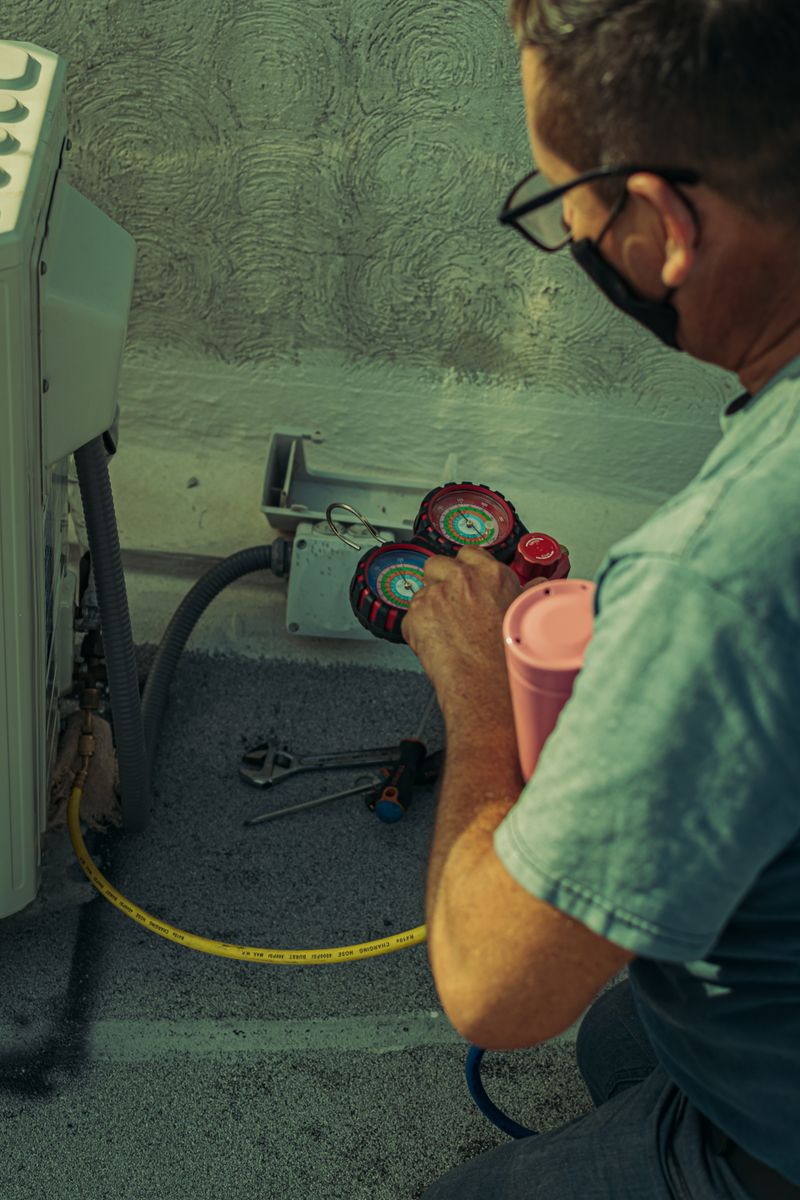
Superheat and subcooling are often displayed side by side on a digital manifold, but they answer different questions. Superheat helps describe the vapor leaving the evaporator; subcooling helps describe the liquid leaving the condenser. Together they can show how the refrigeration circuit is behaving—if the technician first establishes trustworthy airflow, load, and operating conditions.
Neither value is a universal charging target. The correct method comes from the current OEM instructions for the exact matched system, refrigerant, metering device, and test condition.
The difference at a glance
| Measurement | Conceptual calculation | Typical measurement area | What it helps evaluate |
|---|---|---|---|
| Superheat | Actual suction-line temperature minus saturation temperature at the corresponding pressure | Suction vapor leaving the evaporator or at another OEM-defined point | Evaporator feeding, vapor condition, and compressor protection evidence |
| Subcooling | Saturation temperature at the corresponding pressure minus actual liquid-line temperature | Liquid leaving the condenser or at another OEM-defined point | Condenser liquid condition and available liquid column evidence |
Use the correct pressure-temperature relationship for the identified refrigerant. Blends may require the appropriate dew or bubble reference as directed by the instrument and manufacturer. Confirm that hoses, probes, manifolds, and refrigerant selections are compatible with the system.
Why airflow comes first
The indoor coil exchanges heat with moving air. A dirty filter, incorrect blower setup, blocked coil, closed dampers, duct restriction, or low indoor load can change coil temperature and pressure. Those changes can make a correctly charged system look abnormal or make a charging fault look like an airflow fault.
The Department of Energy lists adequate airflow matched to refrigerant capacity and correct refrigerant charge as separate parts of quality installation. A defensible sequence verifies filter and coil condition, blower setup, duct condition, and airflow evidence before making a charge adjustment.
An HVAC static pressure test can help locate restrictive airflow conditions. Correct them and repeat the refrigeration measurements under stable operation.
How metering devices affect the method
Fixed-orifice systems
A fixed orifice does not actively regulate evaporator superheat. Many such systems use an OEM target-superheat procedure that accounts for indoor and outdoor conditions. The target must come from the equipment chart or approved service method—not a remembered rule of thumb.
TXV or EEV systems
A thermostatic or electronic expansion valve regulates evaporator feeding within its operating range. Many systems with these devices use an OEM target-subcooling procedure for final charge, but that does not make subcooling the correct method for every TXV or EEV application.
The valve can also mask or imitate other faults. A technician should not condemn a metering device until sensing, airflow, pressure drop, charge state, control inputs, and the manufacturer’s diagnostic steps have been evaluated.
A conditions-first diagnostic workflow
Refrigerant-circuit work must be performed by properly certified personnel. EPA states that connecting or disconnecting gauges and hoses, adding or removing refrigerant, and other work expected to open the circuit require Section 608 certification. Intentional venting is prohibited except for narrowly defined permitted releases.
1. Identify the system and approved procedure
Record the outdoor and indoor model numbers, refrigerant, metering device, line-set configuration, and any factory or field charge information. Obtain the current charging chart and confirm whether it calls for superheat, subcooling, weigh-in, or another process.
2. Establish airflow and load
Confirm clean heat-transfer surfaces, filter condition, blower command, static-pressure result or other approved airflow evidence, open registers, and stable indoor load. Note staging, zoning, humidity mode, and any control behavior that changes capacity.
3. Stabilize operation
Allow the system to operate for the time and condition specified by the manufacturer. Record indoor and outdoor conditions, stage, pressures, line temperatures, and probe locations. A screenshot without conditions is not a complete charging record.
4. Calculate with trustworthy inputs
Use calibrated, properly rated instruments and good thermal contact at the required locations. Confirm the selected refrigerant and the correct saturation reference. Inspect for temperature-probe influence from outdoor air, solar loading, loose attachment, or poor insulation.
5. Interpret a pattern, not one value
Compare superheat, subcooling, suction and discharge pressures, line temperatures, temperature split, airflow evidence, compressor operation, and the OEM chart. Then investigate the most plausible causes before changing charge.
Reading patterns without universal shortcuts
| Pattern | Possible explanations to investigate |
|---|---|
| Higher superheat with lower subcooling | Low refrigerant mass, feed restriction, low liquid supply, measurement error, or operating condition outside the chart |
| Lower superheat with higher subcooling | Excess refrigerant, overfeeding, airflow or load problem, control issue, or incorrect measurement condition |
| Higher superheat with higher subcooling | Liquid-line or metering restriction, feed problem, receiver or circuit configuration, or sensor error |
| Lower superheat with lower subcooling | Low load, airflow condition, overfeeding with insufficient liquid reserve, compressor or control issue, or unstable operation |
This table is a starting hypothesis list, not a charging chart. Different system designs can produce different relationships. Do not add or remove refrigerant solely because one cell appears to match.
Common charging mistakes
- Adjusting charge before confirming airflow and coil cleanliness.
- Using a generic target instead of the exact equipment chart.
- Selecting the wrong refrigerant or saturation reference on a digital manifold.
- Measuring during startup, defrost, capacity transition, or unstable load.
- Ignoring line-set length, installed accessories, and the matched indoor coil.
- Treating a clear sight glass, compressor current, or pressure alone as proof of correct charge.
- Adding refrigerant to a leaking system without finding and repairing the leak.
Copeland’s condensing-unit commissioning guidance calls for stable operation and considers suction and discharge pressures, superheat, and subcooling together; it specifically cautions against charging by compressor-current measurement. The exact residential procedure still comes from the installed equipment manufacturer.
Document the final condition
A useful service record includes:
- Indoor and outdoor model numbers and refrigerant.
- Metering device and operating mode or stage.
- Indoor and outdoor air conditions.
- Verified airflow evidence and filter condition.
- Suction and liquid pressures and line temperatures.
- Calculated superheat and subcooling with probe locations.
- OEM target or chart reference.
- Refrigerant recovered or added under the approved procedure.
- Final leak check and operational verification.
If your instruments need updating for current refrigerants, compare compatibility and features in our HVAC manifold gauge guide. For A2L equipment, also follow the A2L refrigerant service safety checklist.
Bottom line
Superheat describes vapor above saturation; subcooling describes liquid below saturation. Their diagnostic value comes from correct inputs, stable conditions, verified airflow, and the OEM charging method. Use both as part of a complete operating picture, not as independent reasons to move refrigerant.
Sources and image credit

ThermalTechPro Editorial Team
Independent trade-focused editorial team