Refrigerant leak detector types: which method to use
Quick answer
No refrigerant leak detector type is best for every stage. First verify the exact refrigerant and equipment instructions. Use a compatible electronic detector or ultrasonic tool to locate the area, then repeat the response and use an appropriate point-confirmation method, such as formulated bubble solution, before documenting the result. UV dye fits selected persistent or intermittent cases only when the dye, lubricant, refrigerant, equipment, and service procedure are compatible.
Common questions
- Which refrigerant leak detector type is best?
- There is no universal best type. A compatible infrared detector is a strong general search tool for many HVAC jobs, while heated-diode and semiconductor models suit other budgets and response preferences. Ultrasonic, bubble, and approved UV methods solve different field problems.
- Can the same detector find R-32, R-410A, and R-454B?
- Only if current manufacturer documentation for that exact model lists the refrigerants and approves the detector for the intended work environment. Never infer compatibility from sensor type, age, or a general A2L label.
- Does a bubble test prove there is no refrigerant leak?
- No. A growing bubble at the exact point is strong location evidence, but no bubbles may simply mean the leak is inaccessible, pressure is insufficient, conditions are unsuitable, or the leak is below that product's capability.
Source note: Reviewed August 2026 against current EPA Section 608 guidance and manufacturer documentation from Fieldpiece, INFICON, NAVAC, Superior Signal, Refrigeration Technologies, and Spectroline. Capabilities cited are manufacturer specifications, not hands-on test results. Always use the current manual for the exact detector and equipment.
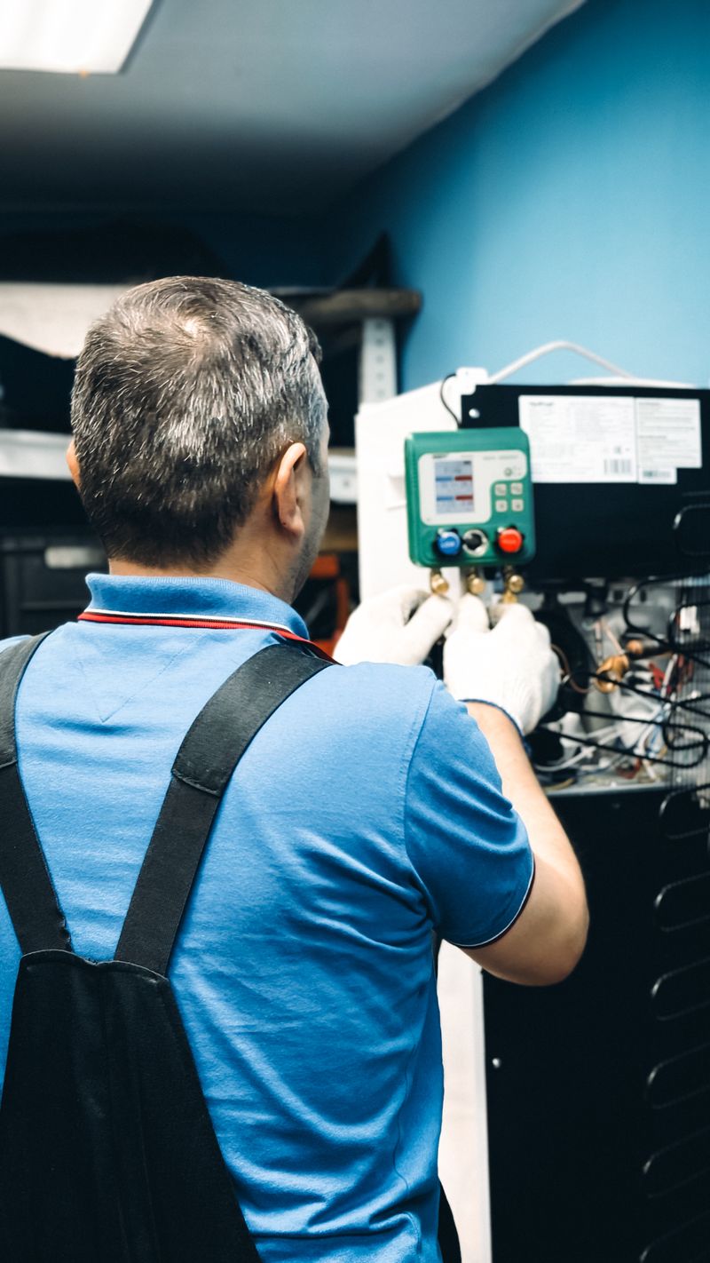
A detector can alarm without pinpointing a repairable leak, and a quiet detector can miss one under the wrong conditions. The useful question is which method fits this refrigerant, environment, and diagnostic stage?
EPA distinguishes evidence that a system may be leaking from methods that locate the leak. Pressure readings and decay tests can support a diagnosis, but they do not identify a repair point. Reliable work moves from broad search to repeatable location to post-repair verification.
Refrigerant leak detector types compared
| Detector type | Best use | Main strength | Important limitation |
|---|---|---|---|
| Infrared electronic | General searching and pinpointing on listed halogenated refrigerants | Long-life sensor and consistent response on many listed refrigerants; some models resist oil and moisture false alarms | Often detects a change in concentration, so probe movement, background control, and model-specific technique matter |
| Heated diode or electrochemical | Sensitive electronic search where a sustained response helps | Strong initial sensitivity; some models can remain over a leak rather than requiring continuous movement | Sensor is consumable, response can vary by refrigerant, and contamination or age can reduce performance |
| Semiconductor | Routine service and lower-cost electronic detection | Broad usefulness and affordable entry point | Compatibility can be narrower than the category suggests; background vapors, contamination, and sensor condition require careful control |
| Ultrasonic | Windy, refrigerant-saturated, or gas-independent searches | Listens for sound from turbulent flow rather than identifying refrigerant | Needs a leak that generates ultrasound and can confuse mechanical or electrical background noise with a leak |
| Formulated bubble solution | Confirming an accessible joint, valve, or suspected point | Visually pinpoints gas flow at the exact surface | Requires access and suitable pressure, temperature, and air movement; a negative result does not clear the whole system |
| UV fluorescent dye | Persistent, intermittent, or difficult leaks where approved dye can circulate with oil | Leaves visible evidence that can remain available for later inspection | Intrusive, may require circulation time, and must match the lubricant, refrigerant, equipment, dosage, and OEM procedure |
Treat the table as a selection map, not a ranking. If you are shopping for a specific electronic tool after choosing a sensor approach, compare current specifications in our HVAC refrigerant leak detector buyer guide.
Start with refrigerant and A2L compatibility
Read the equipment label and service instructions first. Verify the exact refrigerant in the detector manufacturer’s current manual or compatibility chart. “Detects refrigerants,” “A2L compatible,” and “safe for the work area” are not interchangeable claims.
For R-32 or R-454B equipment, use the A2L refrigerant service safety checklist to check tools, ignition control, ventilation, and mitigation features. An alarm near one A2L refrigerant does not prove the tool detects every A2L or hydrocarbon refrigerant.
How each detection method fits the job
Infrared electronic detectors
An infrared detector measures how a sample absorbs infrared energy. It can be a strong primary choice across multiple listed refrigerants. Refrigerant range and false-alarm resistance belong to the model—not every infrared detector.
Technique is critical. The current Fieldpiece DR82 manual directs users to start in refrigerant-free air, complete warm-up, move the tip at about 3 inches per second, clear it after an alarm, and return for the highest repeatable value. This model responds to a concentration change, so leaving its tip stationary can mislead.
Heated-diode and electrochemical detectors
These designs use a heated sensing element to respond to halogenated refrigerant. They can provide a sustained indication when a technician dwells over a suspected point. The INFICON Compass manual identifies an electrochemical heated-diode sensor and automatic background adjustment.
The sensor is consumable: sensitivity can fall with age, and response may differ among refrigerants. Check the reference-leak procedure, replacement interval, filter, warm-up, and refrigerant list before trusting a negative result.
Semiconductor detectors
Semiconductor models suit routine work and backup kits, but the category does not prove universal compatibility. NAVAC lists its NML1 for R-32/R-454B while excluding HFOs and blends with more than 50% HFO content.
Follow the model’s warm-up and calibration procedure, keep the probe out of oil and liquid, and retest after the sensor clears. If background concentration rises, follow the approved ventilation or isolation procedure instead of repeatedly zeroing away the signal.
Ultrasonic detectors
Ultrasonic instruments listen for high-frequency sound from turbulent gas flow. They can search for refrigerant, dry nitrogen, or another permitted test gas and can help where wind or a refrigerant-saturated cabinet confuses a sniffer.
Their weakness follows the same principle: no turbulent sound means no ultrasonic indication. Pressure differential, opening geometry, fans, valves, bearings, and electrical equipment can affect the result. Approach from different angles, reduce sensitivity as the sound strengthens, and confirm the point another way.
Bubble solutions
A purpose-made bubble solution confirms accessible fittings, valves, joints, and coil areas. Apply and clean it according to its label. Refrigeration Technologies notes that microleaks may take 5 to 30 minutes to form a small cluster with its Big Blu product.
Do not substitute household soap without manufacturer approval. Residue, corrosion risk, temperature, wind, and poor access can undermine the test. A growing bubble is useful evidence; an unchanged surface does not clear the circuit.
UV fluorescent dye
UV dye can help with intermittent leaks after an approved product circulates with system oil. Escaping dye leaves a fluorescent trace for later inspection when an electronic signal is difficult to reproduce.
Dye is not a universal first step. Confirm OEM acceptance, refrigerant and lubricant compatibility, formula, dose, injection method, and circulation time. A qualified technician must add it. Fluorescent dye and leak sealer are different products.
Field workflow: locate, confirm, verify
- Establish a leak basis. Rule out airflow, control, and operating-condition problems before treating low pressure or ice as proof. Start with the AC refrigerant leak symptoms workflow.
- Identify the system. Record the equipment, exact refrigerant, charge context, accessible components, and current OEM instructions.
- Select and prove the tool. Confirm refrigerant and A2L compatibility, inspect the sensor and filter, check battery state, complete warm-up, and run the manufacturer’s functional test.
- Search from broad to narrow. Control drafts where permitted, scan likely leak areas using the specified speed and distance, then reduce sensitivity or background interference as the signal strengthens.
- Demand repeatability. Clear the sensor, return from another direction, and identify the same point again. Separate refrigerant movement through a cabinet from the physical source.
- Confirm the point. Use a compatible second method when conditions allow—often formulated bubble solution on an accessible pressurized point. Use dye or ultrasonic testing when the approved workflow calls for it.
- Repair and verify. Follow the OEM procedure, recover rather than vent refrigerant, test the repair, and document the final result. A successful repair check is a separate step from initially locating the leak.
Control common false alarms and missed leaks
- Keep electronic probe tips out of oil, water, cleaner, sealant, and debris.
- Test in clean air and understand how the model zeros against background refrigerant.
- Shield the search from drafts only when doing so is safe and permitted.
- Replace filters and consumable sensors on condition and schedule; verify operation with the maker’s approved reference method.
- Recheck coils, valve caps, service ports, brazed joints, distributors, and concealed sections systematically instead of chasing the loudest first alarm.
- Record a negative test as “not located under these conditions,” not “no leak exists.”
Service handoff checklist
A useful technician-to-customer or shift-to-shift handoff records:
- Equipment model, refrigerant, operating state, and test conditions.
- Detector make, model, sensor type, compatibility source, and functional-check result.
- Search and confirmation methods used, with the exact leak location and repeatability evidence.
- Areas that were inaccessible or could not be tested under valid conditions.
- Repair performed, post-repair verification method and result, and any required follow-up.
- Refrigerant recovered or added, where applicable, plus photos and OEM procedure references.
For homeowners, ask for the location and evidence, not just “low charge.” Then use the AC refrigerant leak repair cost guide to compare a complete repair scope with any replacement proposal.
Your next step
Technicians should stock a compatible electronic tool, point-confirmation method, current manuals, service parts, and documented A2L process. Homeowners should record symptoms, then use an EPA-certified technician.
Never vent refrigerant or open a sealed circuit without the required qualification, recovery equipment, and approved procedure. A reliable result is compatible, repeatable, and documented.
Sources and image credit
- EPA: Refrigerant Management Program questions and answers
- EPA: Section 608 technician certification requirements
- EPA: Prohibition on venting refrigerants
- Fieldpiece DR82 infrared detector operator’s manual
- INFICON Compass electrochemical heated-diode detector manual
- NAVAC NML1 semiconductor detector documentation
- Superior Signal AccuTrak VPE ultrasonic detector documentation
- Refrigeration Technologies Big Blu bubble solution instructions
- Spectroline HVAC/R fluorescent leak detection guidance
- Image: Bulat843 on Pexels

ThermalTechPro Team
Independent trade-focused editorial team